QR Code Sub-module Coloring
ZXing library (Zebra Crossing) can be seen as a dependency on the Android Open Source Project [1], and is used for the decoding of QR codes. If we go to analyze the algorithm that the library follows to decode a QR code, the first step is to binarize the image coming from a camera, and this is done using a ‘dynamic’ threshold based on the luminance of the image.
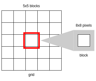
The class HybridBinarizer uses 5x5 blocks to compute local luminance where each block is 8x8 pixels. The following algorithm is based on such class. The image is divided in blocks of 8x8 pixels. Thus we have the number of blocks $N$ that fit inside an image, and it computes a matrix of black points with size $N \times N$, which seems to be the average luminance of the values in the blocks. The average is calculated generally as:
for i in N:
    for j in N:
        avg
        for r in BLOCK_SIZE:
            for c in BLOCK_SIZE:
                avg += luminance
        avg /= BLOCK_SIZE * BLOCK_SIZE
        ...
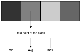
Then, with the above calculation we can get the maximum and minimum values of luminance of the computed block, and if the difference between that maximum and minimum is smaller than $\frac{255}{24}$, since ZXing’s equivalent variable is 24 in a scale from 0 to 255 and we are working with a scale from 0 to 1, then the average is equal to $\frac{min}{2}$. This means that the variation within the block is low, and thus this must be a block with only light or dark pixels. Therefore, if we use the average as its threshold, we are creating noise data instead of guessing the actual module color. That is why in this case the average is half the minimum, assuming that the block is white. Then this assumption is corrected by computing the average black point from the 8 neighbours around the current block’s black point, and if that average is larger than the minimum luminance, the black point becomes that average. That is how the matrix of black points $bp$ with size $N \times N$ is calculated.
for i in N:
    for j in N:
        avg
        for r in BLOCK_SIZE:
            for c in BLOCK_SIZE:
                avg += luminance
        avg /= BLOCK_SIZE * BLOCK_SIZE
        if max - min < MIN_DYNAMIC_RANGE:
            avg = min / 2
        avgBP
        for r in range 3:
            for c in range 3:
                avgBP += bp[i, j]
        avgBP /= 9
        if avgBP > min:
            avg = avgBP
        bp[i, j] = avg
The black point $bp$ is used now to calculate the average black point for each block using a 5x5 grid of the blocks around each block. We calculated the (corrected) average for each block and then it was averaged with a 5x5 block grid.
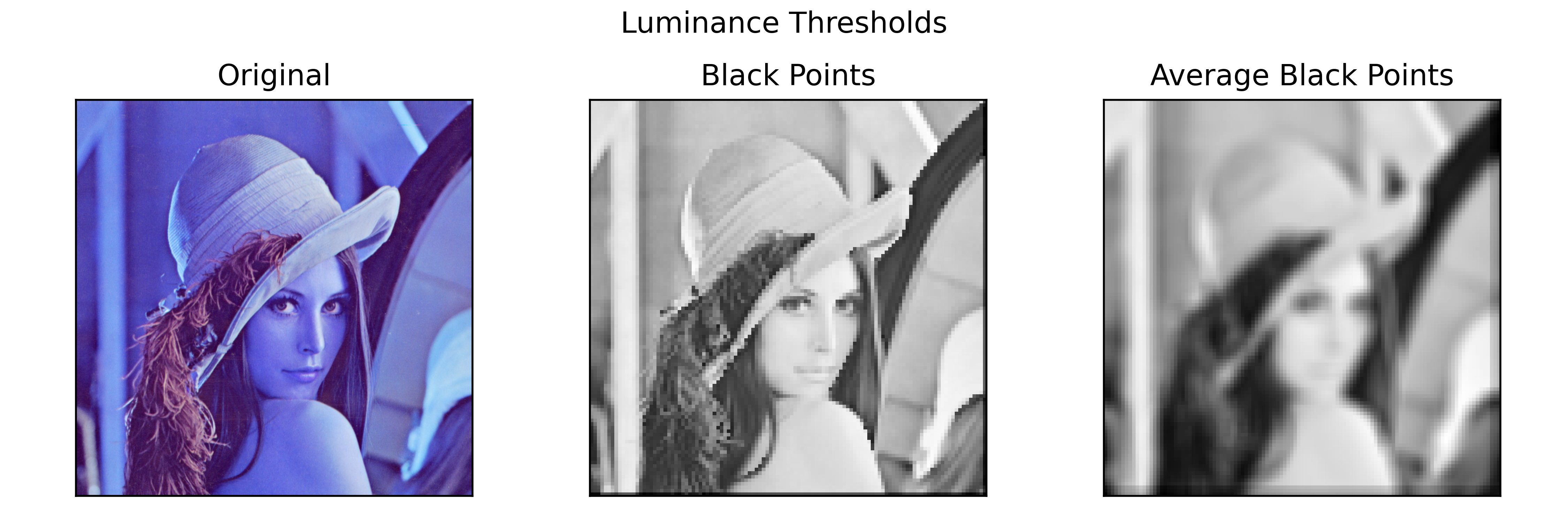
The resulting matrix is the matrix of block averages that is used as thresholds for the binarization. The averages for the blocks tells us the limit from which a higher or lower value is binarized to be white or black. Thus, the averages are the limits of the color from which we need to base the color of the submodule. That is, the average of a block is the mid point from which a value is considered white or black.
How may this $bp$ be applied to the QR embedding? The idea behind computing the thresholds/averages stored in $bp$ is that now we know above or below from what point will the color in a submodule be considered white or black, and thus the averages are now the limits from which to calculate the colors of the submodules.
Coming back to the embedded image $f$, the dimensions are $h \times w$, and the $bp$ matrix has dimensions $N \times N$, where each average $bp_{i,j}$ is the average that corresponds to the 8x8 pixel block in the image located at $f(i:i+8, j:j+8)$. Using this, we can map the matrix to match the dimensions of the image $f$ and thus we can get the corresponding average luminance of any pixel $f(i, j)$. The output of this mapping of $bp$ to size $h \times w$ is an image with the sub-window averages.
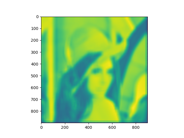
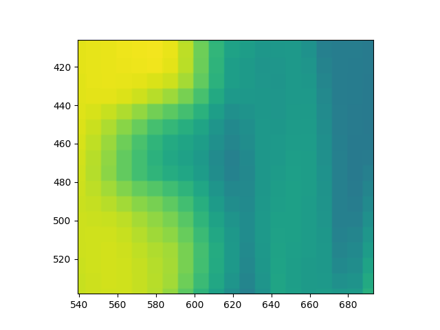
If we zoom in, each 8x8 pixel block in said image appears to have the threshold against which a pixel is compared to in order to determine if it’s considered black, in case that the pixel value is smaller than the value, or white, for the cases where the pixel value is higher.
Therefore, after we compute the overlay alpha module image and before applying the blue noise mask, we must paint the submodules of size $d_a \times d_a$ following the mapped $bp$ image. We did that in the same loop where the average of the colored image together with the submodules and alpha modules. That average, for the sake of documentation, was performed by calculating a three-channel color in RGB color space by averaging each channel in the module. The result is the following.
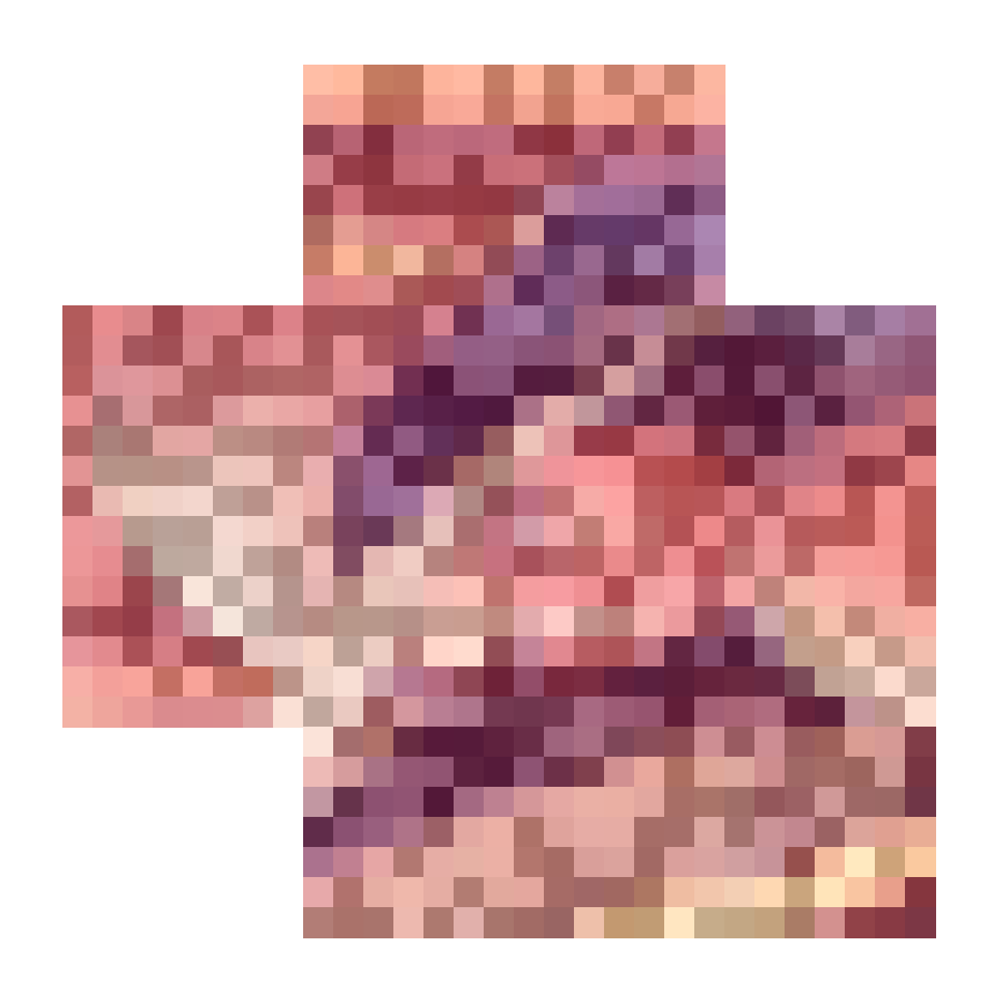
This computation was set as the color of the submodule, but that QR code submodule coloring did not work, because the average computed is not the color of the submodule, if anything, it was just the limit from which the decoder may be determining whether a module is dark or white. That computation will soon be removed. For the time being, that loop is used for this new threshold algorithm.
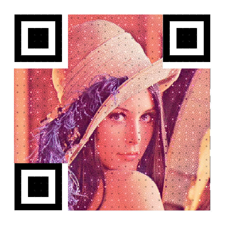
We proceed to paint the submodule inside the QR code image embedding using the luminance stored in the average black point matrix cell $bp(i, j)$ where i,j are the coordinates of the top left corner pixel where the sub-module of size $d_a \times d_a$ begins. Keep in mind that the mapped matrix only contains the average luminance for each pixel $f(i, j)$, so the coloring of the submodule is calculated as the RGB value of an HSV color space value, with the H and S being the hue and saturation of the pixel $f(i, j)$ in the original image, and the L value is the average stored in the mapped matrix for that pixel. The result of this coloring produces a QR code that works slower, but works.
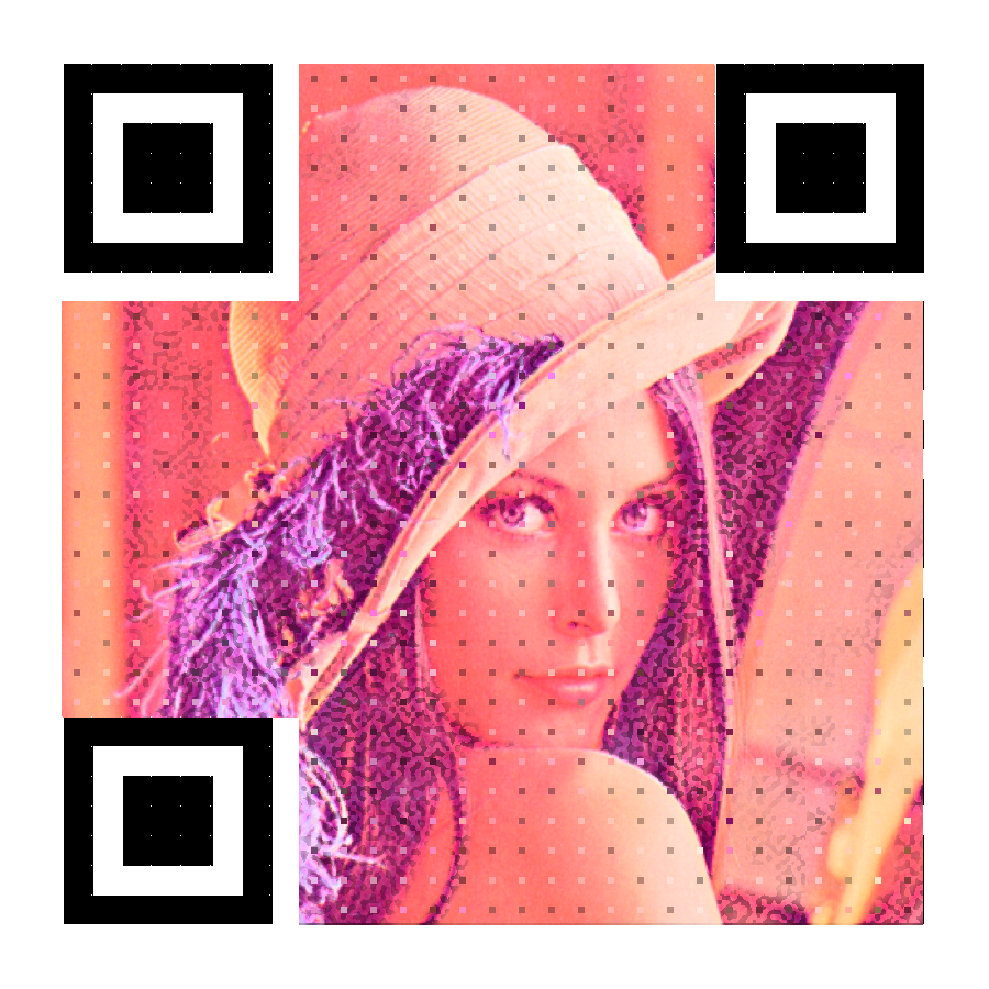
Then, if we change the size of the white noise from which we generate the blue noise mask, we get a smaller grained pattern, plus the average black point of luminance in the mapped matrix. It gives us the following QR code that works if you get a little closer.