Coding Letters On A Path
The challenge now is to make letters paint the frame on its own. For that, I got the references that Design uses:
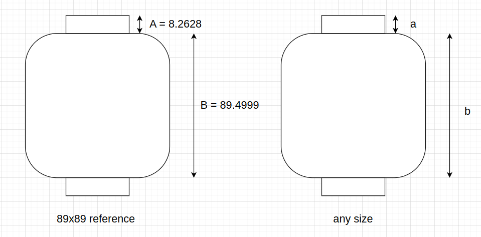
Therefore, we need to generalize the proportions of the figures for all sizes. The first thing to do was
\[\frac{B}{A} = 10.83 = \hbox{B is 10.83 times what A is}\]By knowing $A$, $B$, and $\frac{B}{A}$, we can know $a$ and $b$, which represent the sections for any image size. But we need to solve a tiny linear equation system:
\[\begin{cases} a + b = \hbox{frameHeight} \\ \frac{B}{A}a = b \end{cases}\]where
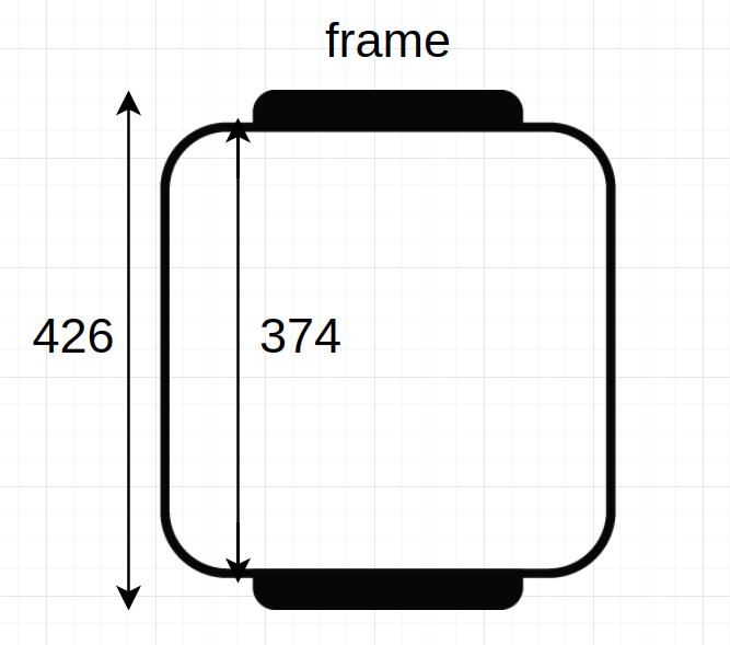
\[\hbox{frameHeight} = (\hbox{inner size} + 2 \cdot \hbox{frame margin}) \cdot \frac{374}{426}\]since the reference measures will be constants in all these computations. That’s how the term $\frac{374}{426}$ came to be, so that the current measure for the image height represented by $(\hbox{inner size} + 2 \cdot \hbox{frame margin})$ is transformed to a $B$ size by following the proportion $\frac{374}{426}$, which is the size of the frame (without the identifiers’ rectangles) over the total image size in the reference (426 px).
This will allow us to solve for $a$:
\[a + \frac{B}{A}a =\hbox{frameHeight} \\ (1 + \frac{B}{A})a = \hbox{frameHeight} \\ a = \frac{\hbox{frameHeight}}{(1 + \frac{B}{A})} \\ b = (\frac{B}{A}) a\]Other constants taken in account involve the distance from the edge of the reference PNG until the actual frame starts, which looks as below.
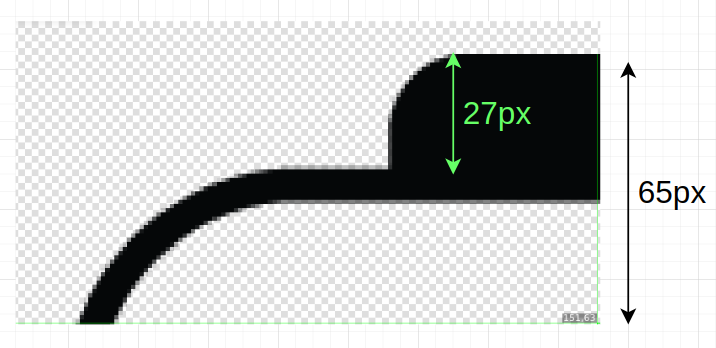
That is why a constant proportion ratio was established as $\hbox{frameDist} = \frac{27}{65}$, which represents the y distance to advance to the point where the actual frame begins. It is also important to point out that
\[\hbox{fullSize} = \hbox{inner size} + (2 \cdot \hbox{frame margin}) + (2 \cdot \hbox{margin left})\]where
\[\hbox{frame margin} = \hbox{target size} \cdot \frac{65}{426}\]since we want to maintain the proportion of an additional 65 px for the frame for an image of size 426x426. Then, it was also noticed that the QR matrix library approximates a QR for the size the user desires, but the output image’s size isn’t necessarily the exact same, there is usually an epsilon, defined as:
\[\epsilon = \hbox{fullSize} \cdot \frac{5}{426}\]Once that we defined all constants and figured out a generalization for $a$ and $b$, we can translate any measure in the reference image to any size, maintaining the proportions in the reference. We can do this translation by doing
\[\hbox{desired measure} = b \cdot (\frac{\hbox{desired measure in reference}}{B})\]For example, to get $n$ and $r$, which both are a generalization for reference measures $N$ and $R$, we would do:
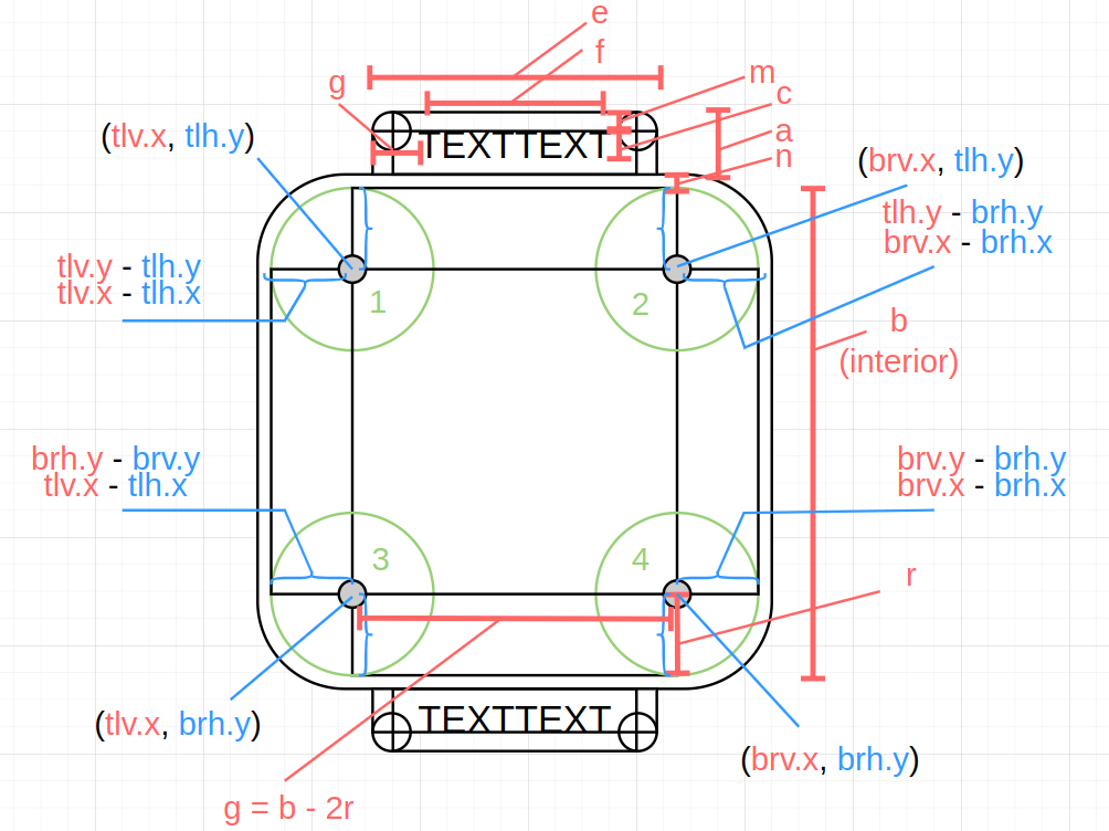
\[n = b \cdot (\frac{N}{B}) \\ r = b \cdot (\frac{R}{B})\]These measures are needed to define the following coordinate points:
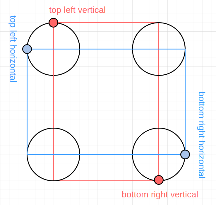
They depend on $matrix->getMarginLeft(), $frameMargin, $frameDist, n, r and the epsilon.
$xTopLeftVertical = $matrix->getMarginLeft() + $frameMargin*$frameDist + $n + $r - $epsilon;
$yTopLeftVertical = $matrix->getMarginLeft() + $frameMargin*$frameDist + $epsilon + $n;

$xTopLeftHorizontal = $matrix->getMarginLeft() + $frameMargin*$frameDist + $n - $epsilon;
$yTopLeftHorizontal = $matrix->getMarginLeft() + $frameMargin*$frameDist + $n + $r - $epsilon + $n;

$xBottomRightVertical = $fullSize - $matrix->getMarginLeft() - $frameMargin*$frameDist - $n - $r + $epsilon;
$yBottomRightVertical = $fullSize - $matrix->getMarginLeft() - $frameMargin*$frameDist - $epsilon - $n*0.5;

$xBottomRightHorizontal = $fullSize - $matrix->getMarginLeft() - $frameMargin*$frameDist - $n + $epsilon;
$yBottomRightHorizontal = $fullSize - $matrix->getMarginLeft() - $frameMargin*$frameDist - $n - $r + $epsilon - $n*0.5;
Since, we mentioned n, it’s important to define the full scheme from which these variables come from:
Then, the next step is to call imageFilledCircledRect(\GdImage $image, int $color, array $verticalRectCoords, array $horizontalRectCoords, array $circleCenters, array $circleRadii) two times in order to create the two circled rectangles that we frame needs, one in the foreground color (ie black) and the background color (ie white). By changing the size of the radii and moving the top left and bottom right corners, we can keep the same circle centers in both circled rectangles.
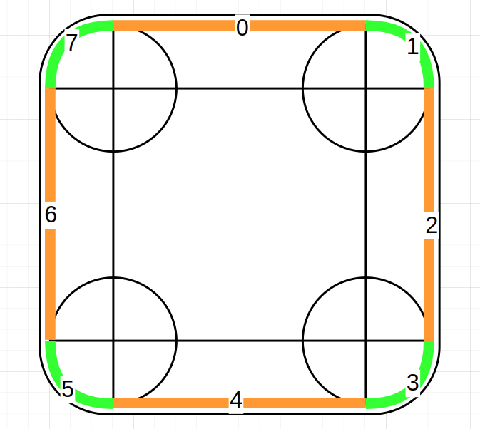
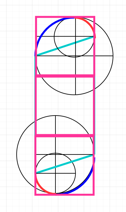
Now the letter placing algorithm can be defined. The first thing to point out is the sections: there are 8 as a total, where 4 are straight sections (orange) and 4 are circled sections (green).
The general notion is that, in a loop (a while loop), each letter is placed in the beginning of each iteration with imagettftext(\GdImage $image, int $size, int $angle, int $x, int $y, int $color, <FONT_PATH>, string $text), and therefore, a coordinate point where the current letter is written must be computed in all iterations. The beginning of each iteration writes a letter. Therefore, we must initialize the start coordinate, so that in the first iteration it is used, and from that point on, at the end of the iterations in the loop, right before moving onto the next, the next coordinate point is computed.
How do we perform the computation of the next coordinate point where a letter must be placed? Let $w$ be the letter width in pixels and $y$ the letter separation gap, also in pixels. The $\Delta_p$ then is the change in position that each iteration signifies, but $\Delta_p$ changes depending on the type of section you are currently in. For straight sections, $\Delta_p = w + y$, but for circled sections, the idea of $\Delta_p$ morphs to $\Delta_a$ or change in angle. The position $(x, y)$ is not accumulated in this sections, and what is accumulated is the angle.
\[x = Cx_i + width_i \cdot cos(\theta_j + \phi) \\ y = Cy_i + height_i \cdot \sin(\theta_j + \phi)\]where
\[\theta_j = \theta_{j - 1} + \Delta_a\]and $i$ refers to the current circle (from a total of 4), $Cx$ and $Cy$ refer to the corresponding x and y values of the coordinate points that make up the 4 known circles’ centers, and $j$ would represent the current iteration in the while loop. It’s important to note that the angle doesn’t change for x and y even though the radius does when it’s an ellipse. Then, the computation of $\Delta_a$ is defined as:
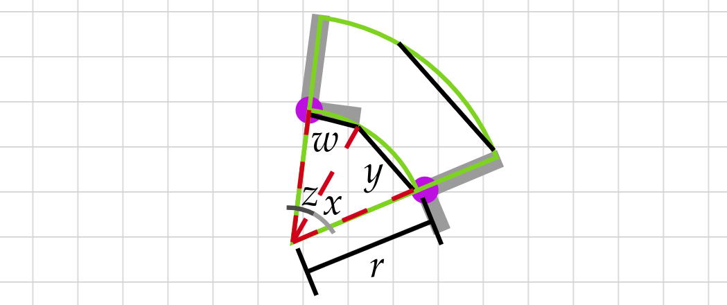
\[\Delta_a = |tan^{-1}\left(\frac{y}{width_i}\right)| + |tan^{-1}\left(\frac{w}{width_i}\right)|\]This definition can be best explained with the diagram below, where the two componets of $\Delta_a$ are represented by $z$ and $x$.
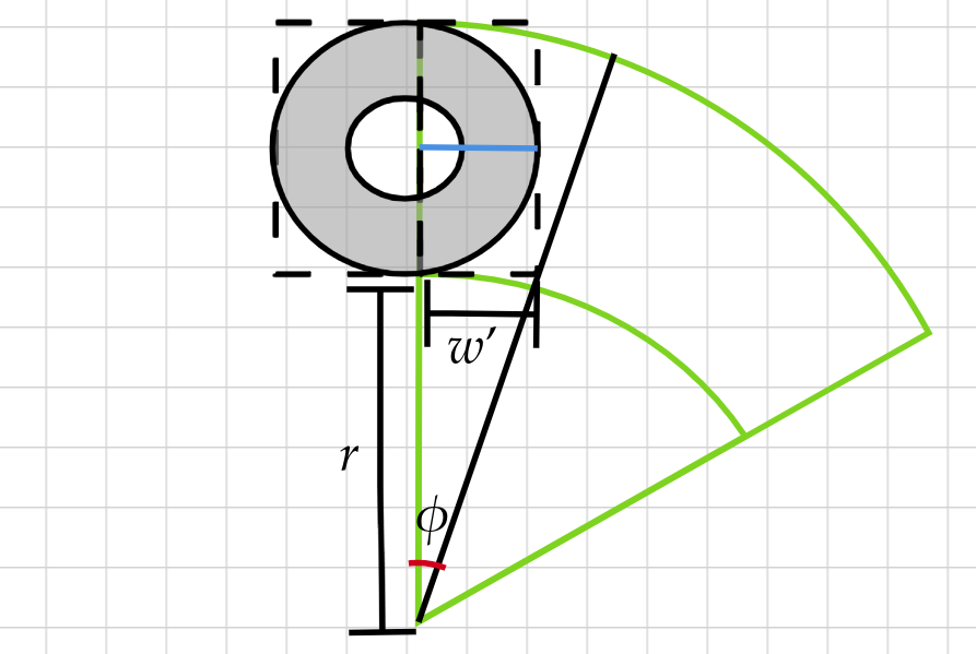
The angle $\phi$ is not accumulated in the definition of $\theta_j$ because it must be added just one time per circled section, since $\phi$ represents the starting angle when the circled section begins. This comes from the fact that, during a straight section, we know the current section’s distance is covered and the section type must change when the distance between current position plus $\Delta_p \times 0.5$ and the starting coordinate of the current section is bigger than the reference masure known as $g$. Therefore, in the last iteration of a straight section, if $\Delta_p \times 0.5$ fits, which means if half a letter fits, we place it as the last letter of that straight section. That means, there exists always a possibility that the straight sections exceed the ideal $g$ by pixels of half a letter of less. Thus, if we were to start each circled sections initial $\theta_i$ as 0, the first letter of a circled section would possibly overlap the last staright sections letter by pixels of half a letter of less. This originated the need for a starting angle known as $\phi$, in order to calculate the starting angle by knowing how much did the last letter of the previous straight section exceeded $g$. We can now define $\phi$ as
\[\phi = |tan^{-1}\left(\frac{\hbox{remaining width}}{height_i}\right)|\]And graphically, its represented as
After defining $\Delta_p$ and $\Delta_a$ plus the idea of sections, we are almost done with all the algorithm’s pieces. One thing to note now is the references for the starting angle of the letters when the section is straight. Since the computation for the starting angle when in circled sections is the sum of the last straight section’s starting angle and $\phi$, the starting angle is marked as -1 for circled sections.
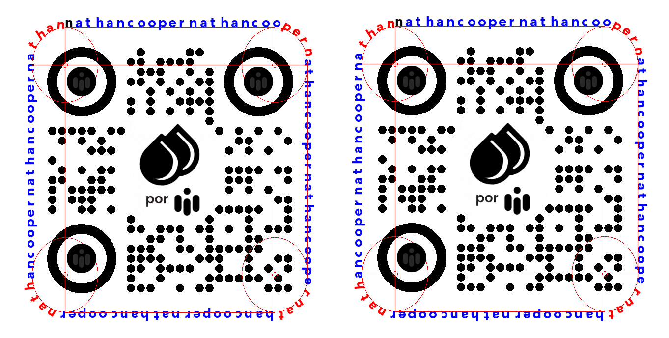
Another note is that, when we know that the circled section distance is covered for the current section, then the following straight section’s starting coordinate, opposite to the coordinate in which the distance will be covered in, must be set to the reference one, not the current x or y in which the circled section finished. For example, if a circled section finished and a straight section along the x axis is following, then the y coordinate must be set to the reference starting point of the section, not where the circled section finished in y. This detail keeps the overall frame centered, avoiding back-propagation of the pixel difference that each section leaves. You can see below and example where this detail is not implemented (left), and also fixed (right).
We mentioned that the angle of the letters in circled sections is always set to -1 in a constant array. This serves the purpose to identify quickly when we are in a circled section, but also because the angle of the letters doesn’t stay constant in these sections, unlike the straight ones. We indeed computed $\Delta_a$ and $\phi$, but these were the angles used for computing the position alongside the ellipse arc, and it’s different from the angle of inclination of the letter. The latter is simply the negative of $\Delta_a$ and $\phi$, that is, the negative of the whole angle we use inside the cosine and sine functions. This can be explained better graphically:

Update: CUDA System
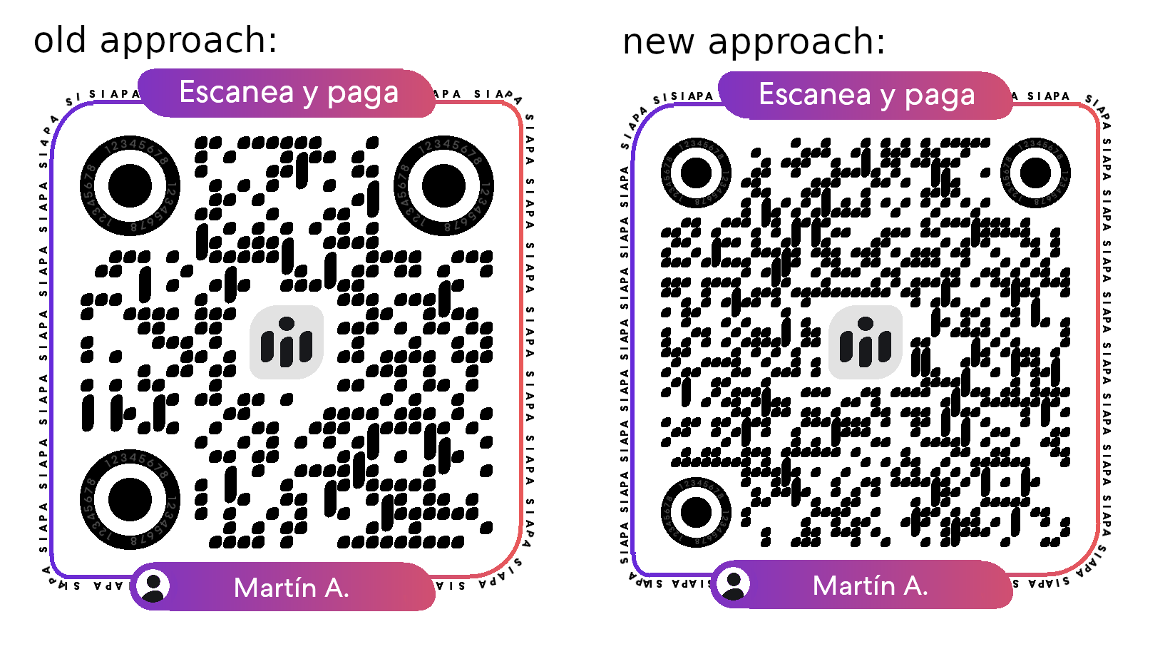
This was ported into CUDA/C++ for better (much better) performance and a new design. The new design reference is this:
The first new change is the circled rect with the radius following $x$ and $2x$ ratio. For this, the easiest way to build it using primitives like squares and rectangles was to create a function called XTrapezoid (pink) and YTrapezoid (blue). The X one means the shift is in the x axis, with the Y trapezoid, the same idea but viceversa.
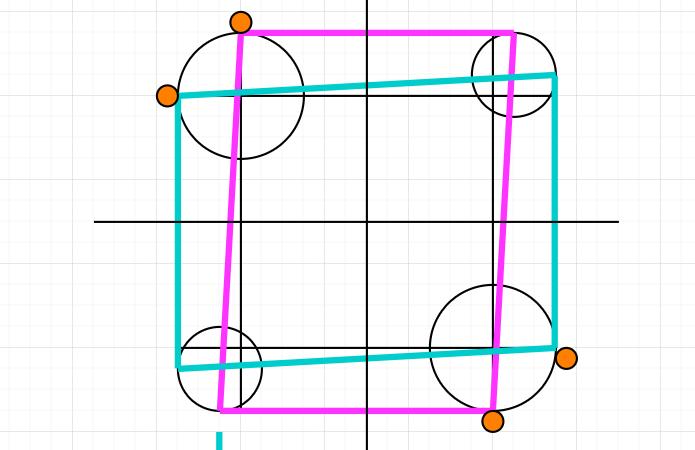
__device__ void XTrapezoid(uchar color, int x1, int y1, int x2, int y2, int xShiftTop, int xShiftBottom, bool isInverse, uchar* imageData, QrCode* qr)
Note: x1, y1 and x2, y2 are the ones marked in orange, which are the points that make up the normal rectangle.
The diagram shows the non-inverse shape of the trapezoids, but the function also accepts a bool that determines, if true, that the trapezoid axis shifting happens inversely. Such inverse x trapezoid is used in both the identifier rectangle shapes:
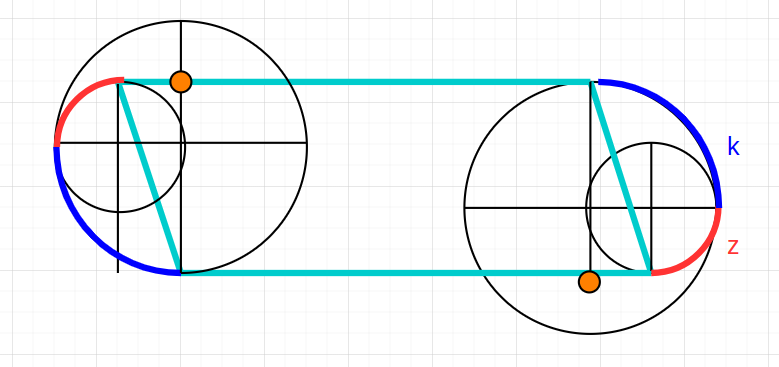
For the construction of the radiuses in the identifier rects, we need to maintain the $x$ and $2x$ ratio, represented by $z$ and $k$ letters, respectively.
Then the data modules. These have a special detail: whenever 4 vertically contiguous modules are found, they become candidates to be painted in a special way (like an ‘i’ shape). This special way is basically 3 of the lower modules of the group painted together as:
and the top module painted as:
Notice that this module design is the one used for any other normal data module in the QR.
A candidate becomes a special group with a probability affected by the number of candidates the current candidate has: the higher the number of neighbours, the less likely the candidate will be painted as a special group. In this way, the modules are spread out so that, given a mass of candidates, only the corner ones (with less neighbours than the center ones) are painted.
Note: this could have been done with a DBSCAN clustering algorithm, where the core point for each cluster would be the candidate that gets painted as a special group. But! Clustering involves a lot of extra data structures, and in CUDA, memory is critical. So for a similar result, the above algorithm was implemented using a recursive function that identifies all vertically contiguous groups of 4 or more as candidates and then decides based on probability as mentioned above.
Update: New Approach To Compute Character Inclination Angle
Ever since the release of this system, the inclination angle for each letter in the circular sections (duh) has not been that good looking.
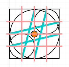
Angles were fixed under the idea that, if the position of the letter along the circled section is correct, then I can compute the angle of the vector that links both the computed position of the char ($A$) and the center of the corresponding circle ($o$) with respect to a reference vector that determines the inclination, in this case $\overleftarrow{oB}$:
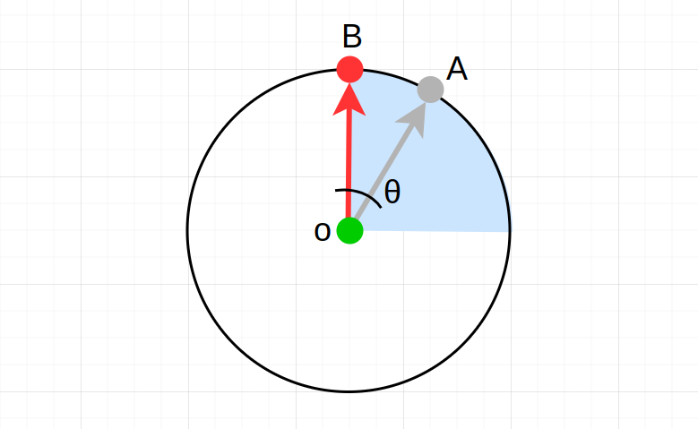
The task in order to find $\theta$ involves knowing the vector from the origin $o$ to point $A$ and the vector from origin $o$ to point $B$, which we will call $\overleftarrow{a}$ and $\overleftarrow{b}$ respectively.
Knowing point $A$ at this point is straightforward: we compute it by the time the letter must be rotated. Origin point $o$ is also known to be one of the four circle centers we got. But point $B$ changes depending on which circle we are on. $B$ points are the following:
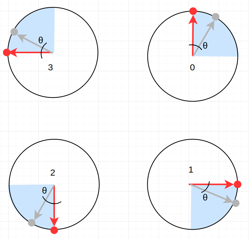
These points are chosen not arbitrarily: they are points along the radius of the current circle that will make the computed $theta$ to be less than 90 degrees, since computers and calculators give out the closest angle to 0 when computing inverse trigonometric functions.
Now, given that we know $o$, $A$ and $B$, we can compute the vectors $\overleftarrow{a}$ and $\overleftarrow{b}$ by:
\[\overleftarrow{a} = \langle A_x - o_x, A_y - o_y\rangle\] \[\overleftarrow{b} = \langle B_x - o_x, B_y - o_y\rangle\]With these two vectors we would be needing this dot product identity:
\[\overleftarrow{a} \cdot \overleftarrow{b} = | \overleftarrow{a} | |\overleftarrow{b} | cos(\theta)\]where we solve for $\theta$:
\[\theta = cos^{-1} \left( \frac{\overleftarrow{a} \cdot \overleftarrow{b}}{| \overleftarrow{a} | |\overleftarrow{b} |} \right)\]I computed this, but suddenly half of the computed angles where NaN! Why was this happening? If we look at the plot for the $cos^{-1}$,
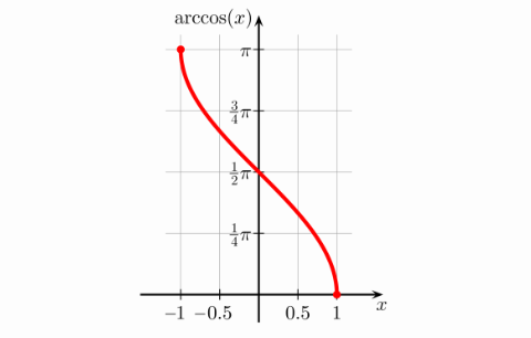
we can see that its domain is $[-1, 1]$, which means that any value smaller than -1 and larger than 1 will be undefined by this function. So, the next problem was: how do we make this fraction
\[\frac{\overleftarrow{a} \cdot \overleftarrow{b}}{| \overleftarrow{a} | |\overleftarrow{b} |}\]to be inside the range $[-1, 1]$? Well, since we know that the dot product is the length of the projection of vector $\overleftarrow{a}$ over vector $\overleftarrow{b}$ and we know that, given the two vectors are unitary, the maximum length of this projection would be one; then if the denominator of this fraction is one (for unitary vectors) then the dot product of two unitary vectors would be the only computation left in this fraction, which would give out maximum 1 and minimum -1. Therefore, in order to make the argument of $cos^{-1}$ inside range [-1, 1], all vectors involved must be unitary.
In this way, the equation can be simplified:
If we have:
\[\overleftarrow{a} = \langle \frac{A_x - o_x}{|\overleftarrow{a}|}, \frac{A_y - o_y}{|\overleftarrow{a}|}\rangle\] \[\overleftarrow{b} = \langle \frac{B_x - o_x}{|\overleftarrow{b}|}, \frac{B_y - o_y}{|\overleftarrow{b}|}\rangle\]Then we just need to compute:
\[\theta = cos^{-1} ( \overleftarrow{a} \cdot \overleftarrow{b} )\]in order to get the needed separation angle between $\overleftarrow{a}$ and $\overleftarrow{b}$.
But this angle is represented in c++ as:
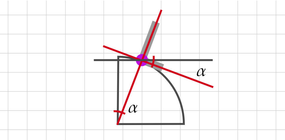
which means the computed $\theta$ is a vector tangent to each computed $A$ point. Therefore, we must substract $\frac{\pi}{2}$ (90°) so that $\theta$ points to the normal vector of the tangent line to each point $A$, which is the desired angle to use for the characters’ inclination.
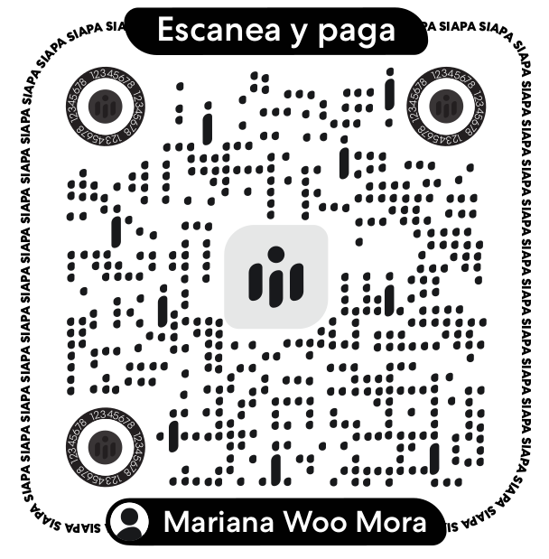
This is the final result where angles look so much more aligned to what they should look like: